[Note: This article refers frequently to the Freescale i.MX233 reference manual, which you can download here.]
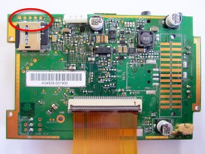
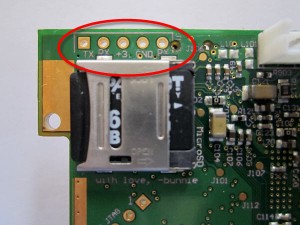
If you disassemble a Chumby One, you will find an easily accessible TTL serial port, shown in the following images:
 |
 |
When I was building my latest Chumby-based robot, I didn’t need the serial port, but I did want PWM signals to control the robot’s wheel motors. Fortunately, the processor pins that are used for the serial (UART) TX and RX pins are multiplexed with PWM outputs. With the proper commands, you can tell the processor to output PWM signals instead of serial TX and RX.
To make the processor output PWM signals, you need to complete four steps:
1. Change the function of the processor pins from UART TX and RX to PWM outputs.
2. Set the duty cycle of the PWM output.
3. Set the period of the PWM output.
4. Enable the PWM output.
You can complete these four steps by using one of two different methods: running regutil, a command line utility, or adding C code to your robot program. Using each method, the following sections describe how to produce a 20KHz signal that is high 25% of the time and low 75% of the time.
Method One – Running regutil
To run regutil, you must download the C source code from the Chumby web site and then compile it yourself to produce an executable.
After compiling regutil, complete the following four steps:
1. To change the function of the processor pins from UART TX and RX to PWM outputs, enter the following command:
regutil -w HW_PINCTRL_MUXSEL3_CLR=0x00f00000
This command clears (sets to zero) bits 23 to 20 of the memory address referenced by HW_PINCTRL_MUXSEL3_CLR, which is defined in regutil_falconwing.h.
The Freescale i.MX233 applications processor in Chumby One is packaged in a 169-pin BGA. Table 37-2 on page 1424 of the reference manual shows that pins 26 and 27 of Bank 1 can function as PWM outputs, inputs to a rotary decoder, serial TX and RX, or general purpose I/O. In it’s default state, the Chumby uses the pins as serial TX and RX.
Table 37-14 on page 1444 of the reference manual PDF shows which bits of the HW_PINCTRL_MUXSEL3 register must be set to activate each function. For example, bits 20 and 21 of HW_PINCTRL_MUXSEL3 control the function of pin 26 of bank 1, which contains the duart_rx signal that we want to change to PWM. Both bits must be zero to change the pin to a PWM output, which you can accomplish by entering the regutil command shown above.
2. To set the duty cycle of the PWM output, enter the following command:
regutil -w HW_PWM_ACTIVE1=0x012c0000
This command says: go high at time 0x0000, and go low at time 0x012c, which equals 300 decimal. Why 300? In the next command you will set the period to 1200 “divided clock cycles”; staying high for 300 divided clock cycles will produce the target 25% duty cycle. The length of a divided clock cycle is set in the next command.
You can find more info about HW_PWM_ACTIVE1 on page 1103 of the reference manual.
3. To set the period of the PWM output, enter the following command:
regutil -w HW_PWM_PERIOD1=0x000b04b0
This command sets the period to 0x04b0 divided clock cycles, which equals 1200 decimal. The length of a divided clock cycle is determined by bits 22:20, which in this example are all zero. These bits indicate how to divide the crystal clock frequency, which is 24MHz. When bits 22:20 are zero, the crystal clock is divided by one, producing a divided clock cycle that is identical to the crystal clock frequency. Thus, each divided clock cycle is 1/24M seconds, which equals 41.7 ns. To get a pulse frequency of 20KHz, 1200 cycles are needed.
You can find more info about HW_PWM_PERIOD1 on page 1104 of the reference manual.
4. To Enable the PWM output, enter the following command:
regutil -w HW_PWM_CTRL_SET=0x00000003
This command enables the two PWM outputs pwm0 and pwm1.
You can find more info about HW_PWM_CTRL_SET on page 1100 of the reference manual.
Method Two – C Code
If you want to use the PWM signals from your robot program, you will want to use C code instead of using the regutil utility. The core procedures in regutil to read and write the i.MX233 registers all well written, but I was able to make a few optimizations:
- Instead of using an array to store the register name and coresponding register address, I used defines. This simplifies the code slightly–no address lookup is required–and the resulting executable will use a bit less memory.
- My code requires that the first parameter of the imx233 procedures be a hex address, not the name of a register. This restriction allows the code can be simplified.
- Naturally, I removed all of the command line parsing code because these procedures are intended be used in a robot program, not at the command line.
The resulting code for the core i.MX233 read and write procedures is shown in the following example. You can find a link to imx233.c, the file containing the core procedures, at the end of this article.
// file: imx233.c
#include <string.h>
#include <stdio.h>
#include <stdlib.h>
#include <sys/mman.h>
#include <fcntl.h>
#include <unistd.h>

int *imx233_mem = 0;

int imx233_rd(long offset) {
   int result;
   static int fd = 0;
   static int *prev_mem_range = 0;

   int *mem_range = (int *)(offset & ~0xFFFF);
   if( mem_range != prev_mem_range ) {
      prev_mem_range = mem_range;

      if(imx233_mem)
         munmap(imx233_mem, 0xFFFF);
      if(fd)
         close(fd);

      fd = open("/dev/mem", O_RDWR);
      if( fd < 0 ) {
         perror("Unable to open /dev/mem");
         fd = 0;
         return -1;
      }

      imx233_mem = mmap(0, 0xffff, PROT_READ | PROT_WRITE, MAP_SHARED, fd, offset&~0xFFFF);
      if( -1 == (int)imx233_mem ) {
         perror("Unable to mmap file");
         if( -1 == close(fd) )
            perror("Also couldn't close file");
         fd=0;
         return -1;
      }
   }

   int scaled_offset = (offset-(offset&~0xFFFF));
   result = imx233_mem[scaled_offset/sizeof(long)];

   return result;
}

int imx233_wr(long offset, long value) {
   int old_value = imx233_rd(offset);
   int scaled_offset = (offset-(offset&~0xFFFF));
   imx233_mem[scaled_offset/sizeof(long)] = value;
   return old_value;
}
Code that uses the imx233 read and write procedures is shown in the following example:
// file: pwm.c
#include
#include
#include "imx233.h"

extern int imx233_rd(long offset);
extern int imx233_wr(long offset, long value);

int main(int argc, char **argv) {

   // If the name of the offset ends in CLR, the bits that are hi will be set to 0.
   // If the name of the offset ends in SET, the bits that are hi will be set to 1.
   // If the name of the offset ends in TOG, the bits that are hi will be toggled.

   // Change the function of the processor pins
   imx233_wr(HW_PINCTRL_MUXSEL3_CLR, 0x00f00000);

   // Set the duty cycle
   imx233_wr(HW_PWM_ACTIVE1, 0x012c0000);

   // Set the period
   imx233_wr(HW_PWM_PERIOD1, 0x000b04b0);

   // Enable the PWM output
   imx233_wr(HW_PWM_CTRL_SET, 0x00000003);

}
This C code produces the same PWM output as the shell commands used in method one.
Conclusion
This article described two methods that you can use to change the function of the serial TX and RX signals to PWM outputs. For interractive debugging, the regutil utility works well. If you want to control the PWM signal from your robot program, the C code method is more appropriate.
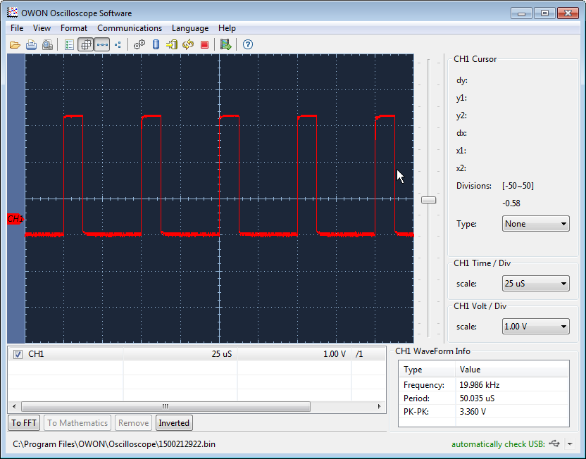
Both methods produce the same result: a 20KHz signal that is high 25% of the time and low 75% of the time. Here is a waveform I captured from my scope showing the PWM signal on the TX pin.
Further Reading
- The reference manual for the i.MX233 application processor is located here (http://www.freescale.com/files/dsp/doc/ref_manual/IMX23RM.pdf?fpsp=1)

Did you see if there’s any other pins available besides the serial port?
The Chumbilical?
In addition to the two serial port pins, there are two other PWM outputs that you might be able to use. One connects the FM radio, and another connects to the top button. In addition, there are 8 general purpose IO pins that are easy to get to. I’ll explain how to access the GPIO pins in a future article.
Every time I type: “regutil -w HW_PWM_PERIOD1=0x000b04b0” and “regutil -w HW_PWM_ACTIVE1=0x012c0000”, nothing is saved.
I’m getting the folowing return: “Setting 0x80064040: 0x00000000 -> 0x00000000 ok” and “Setting 0x80064030: 0x00000000 -> 0x00000000 ok”
Even after enabling PWM outputs, nothing happens. What is happening?
Thanks!
Never mind. I forgot to clear bits 31 and 30 from CTRL register. It worked!
I’m glad you got it working!
Is it possible to create a 50Hz signal to control analogue servo’s? I think you have to change the period but it is not clear for me.
Yes, you could do that. You first have to change the period by setting HW_PWM_PERIOD1. In my example, I needed a 20KHz signal, so I divided 24M by 20K to get 1200 as the value for HW_PWM_PERIOD1. You would divide 24M by 50. Let’s call the result N. (Don’t forget the convert the result to hex.) Next you need to calculate HW_PWM_ACTIVE1. Leave the last bits at 0000. The first bits would represent some fraction of N that represents how long you want the pulse to stay high. For a servo, you high pulse will be around 2 ms. That’s about 0.1N. (Again, don’t forget the convert the result to hex.)
Thank you very much!
This is mine solution:
N is 480.000 so hex. it will become 0x75300. This is to big to put it in the period register. Therefore I also use the CDIV in the period register and put it on DIV_16 => you get a 4 bit shift.
The active register is:
0x00000BB8
Nice solution!